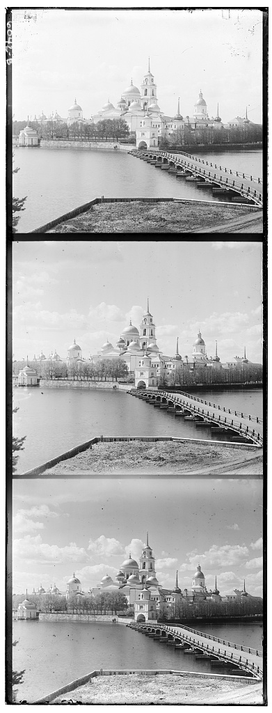

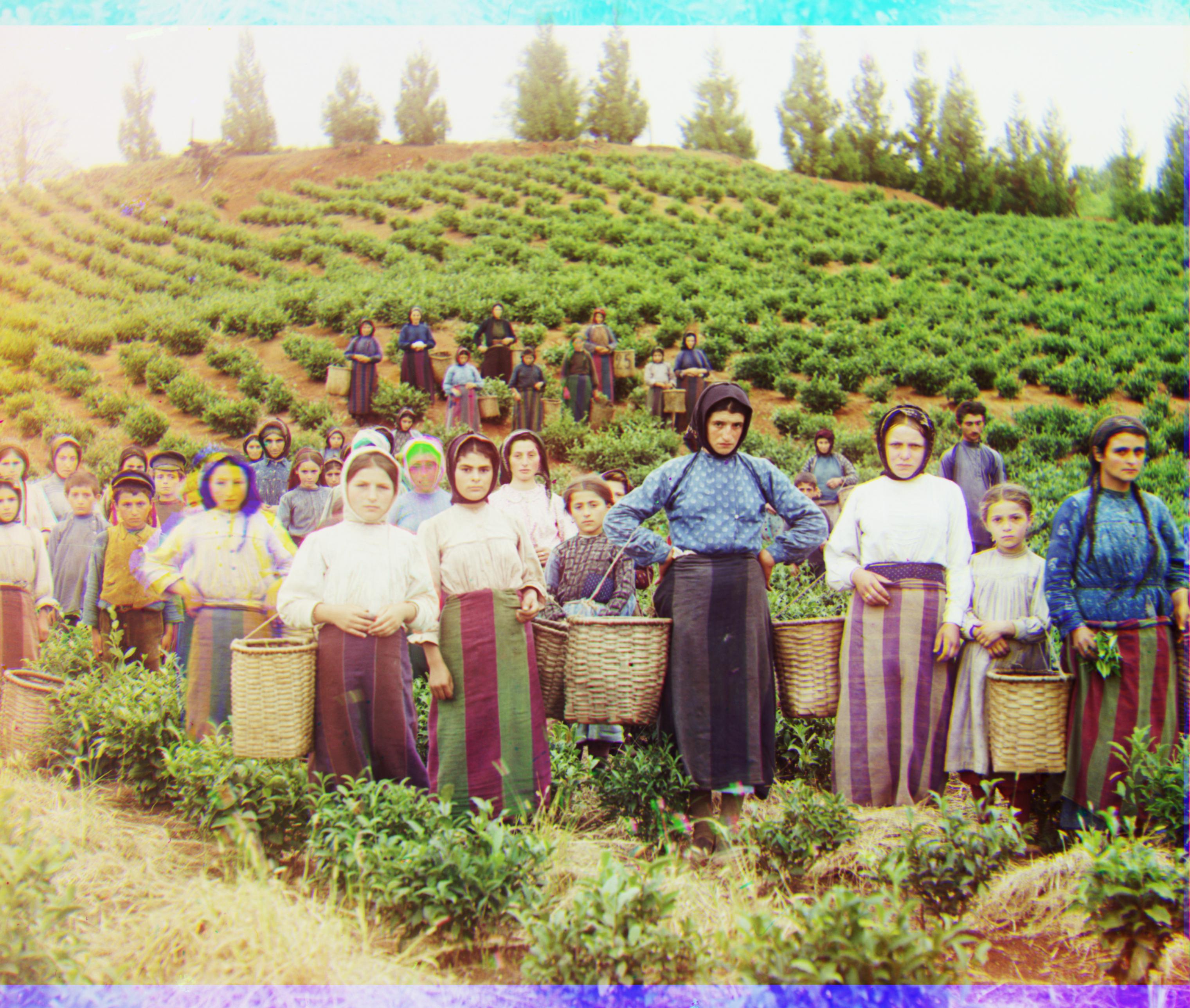
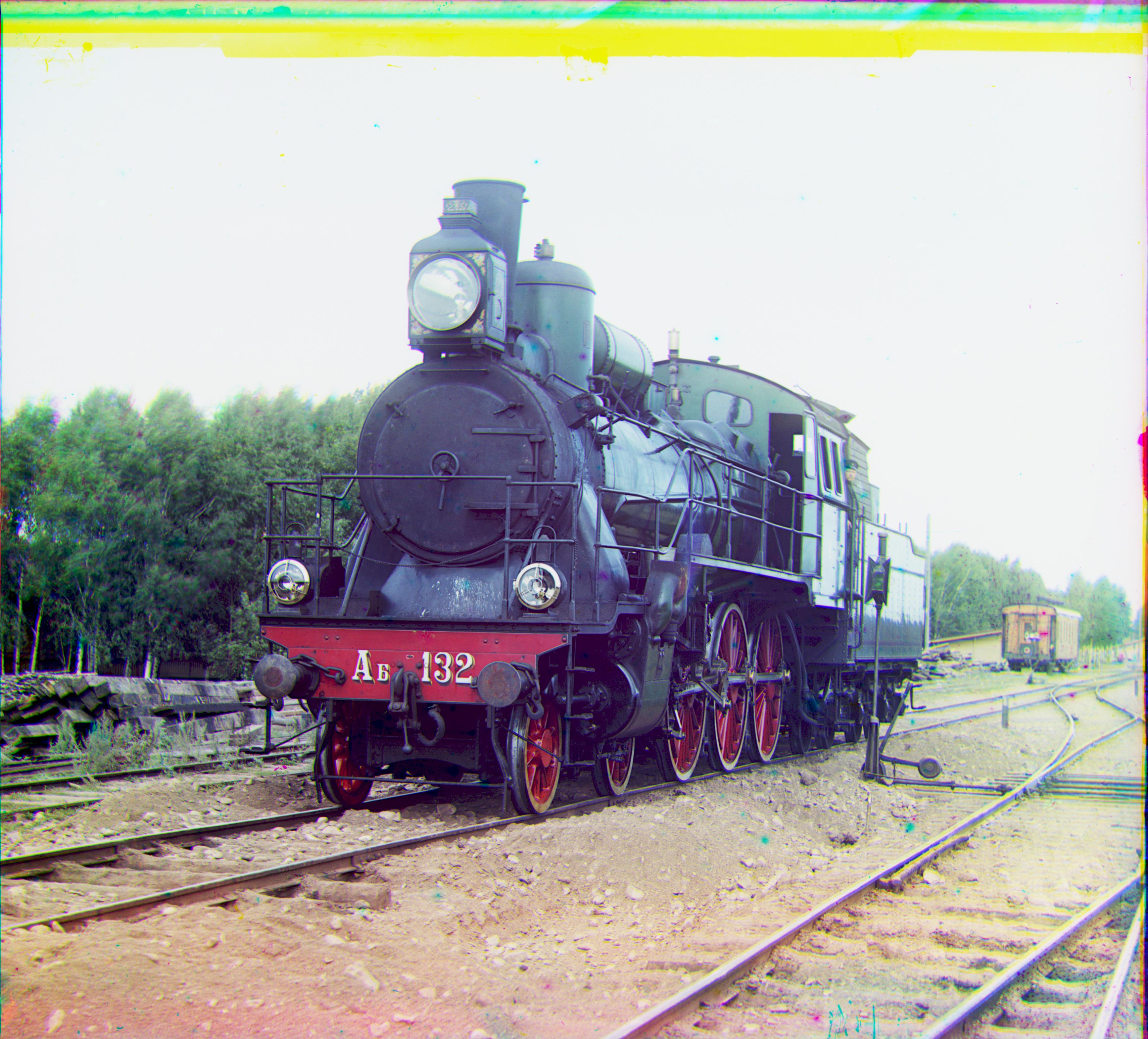
Using Sergei Mikhailovich Prokudin-Gorskii's glass plate image collection , each containing red, green, and blue filtered images, I implemented a program that colorizes and combines the filters into a single, colorized image. This requires finding the best alignment between the three filters, and assigning each filter their respective red, green, and blue channel in order to produce the output as shown below:

|

|
In order to produce a clear image with as few blemishes as possible, we had to calculate how much we need to shift one color channel's image to match the other. We kept track of the optimal displacement vector by overlapping one displaced color channel image over the other, then found the difference between their pixel values. We aim to find the smallest difference between the pixel values to achieve optimal alignment.
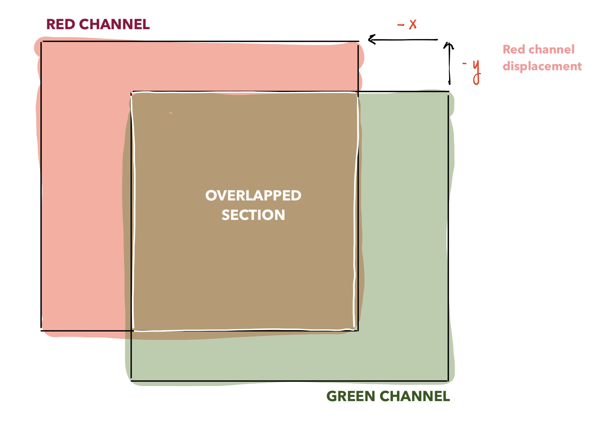
The difference of the pixel values were calculated with the L2 norm, divided by the size of the overlapping window between the two channels to preserve proportionality. For example, if we are aligning the red channel with the green channel,
assuming that the red channel has been displaced by some amount and both the red and green channels cropped into their overlapping window already.
There are two methods to align the channels. The first is a brute-force method of finding the best alignment within a -15 by 15 window of possible pixel displacements. This tends to work well for smaller images, but for larger images, the program runs a lot slower. Thus, we introduce the pyramid method, where we shrink the two color channels to a smaller image, find the optimal displacement out of all possible alignments or a window of -15 by 15 pixels (whichever is smaller), then in the next recursive step, enlarge the channels and the new displacement vector by a factor of two and fine-tune the displacement vector from before. At the final step, the channels should be the same resolution as the original, and we return the displacement vector.
There were a few key fixes that drastically improved the final quality of our image. The first was aligning the red channel and blue channel with respect to the green channel, instead of aligning the red channel and green channel with respect to the blue. Another was to index the channels during alignment to only consider the pixels that were being overlapped instead of cycling pixel values from front to back. Lastly, dividing the L2 norm difference by the size of the overlapping window helped to normalize differences that have more overlap or less overlap. Lastly is to blur the channel image before shrinking it down in order to prevent any issues with aliasing while performing the aliasing method.
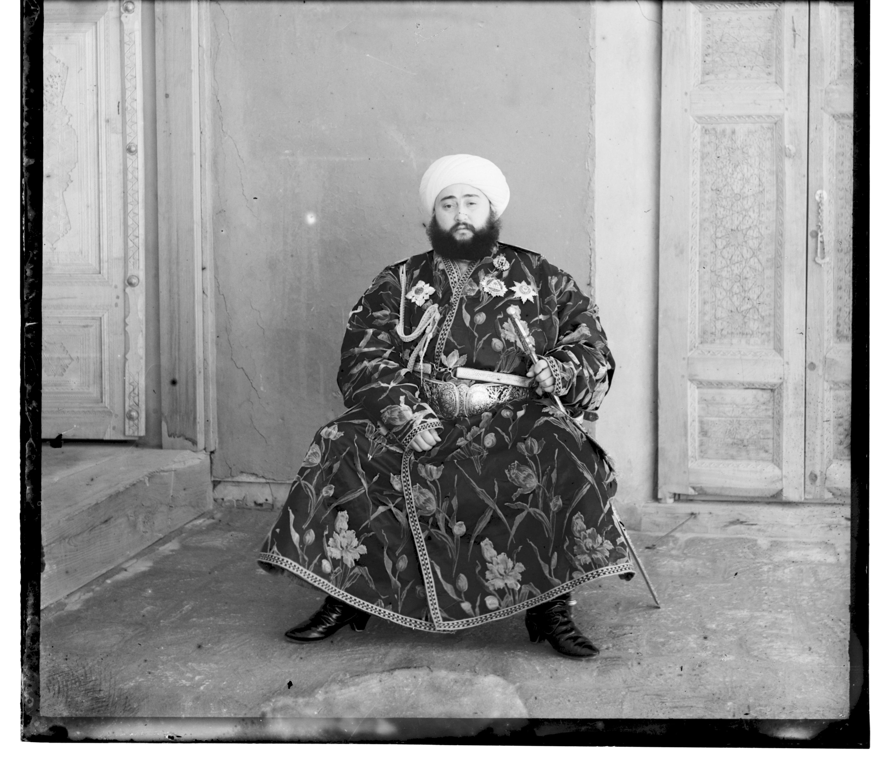
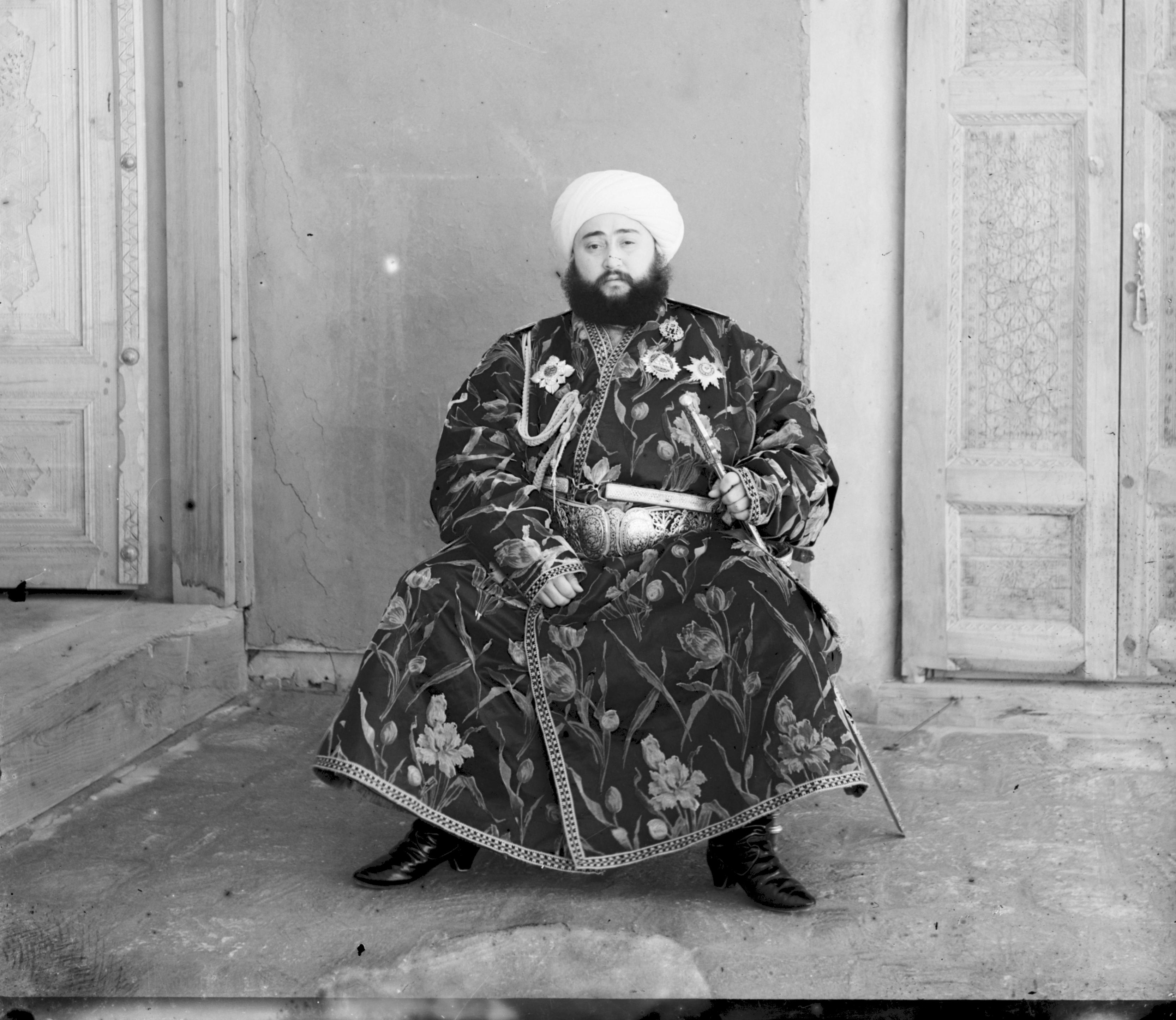
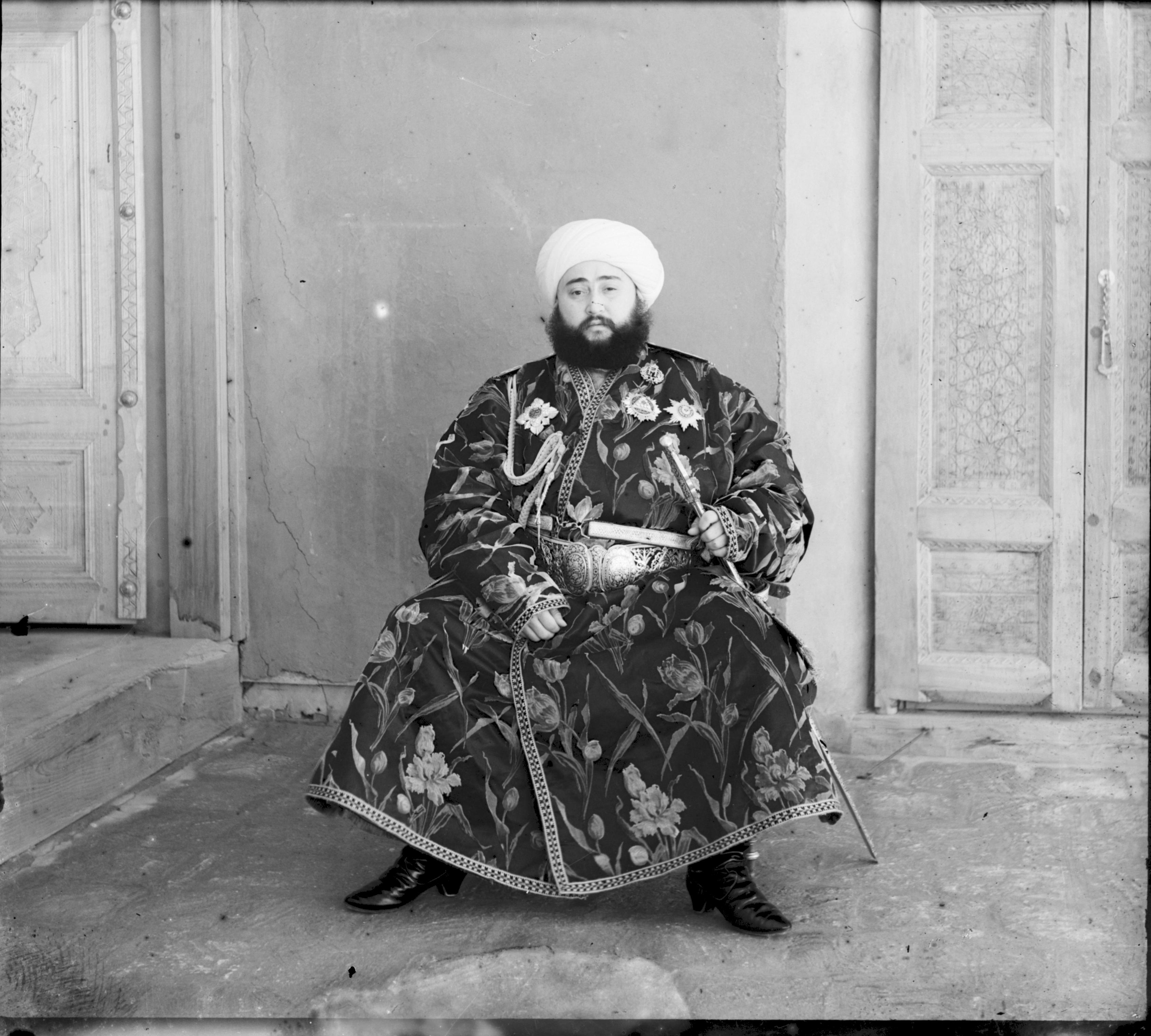
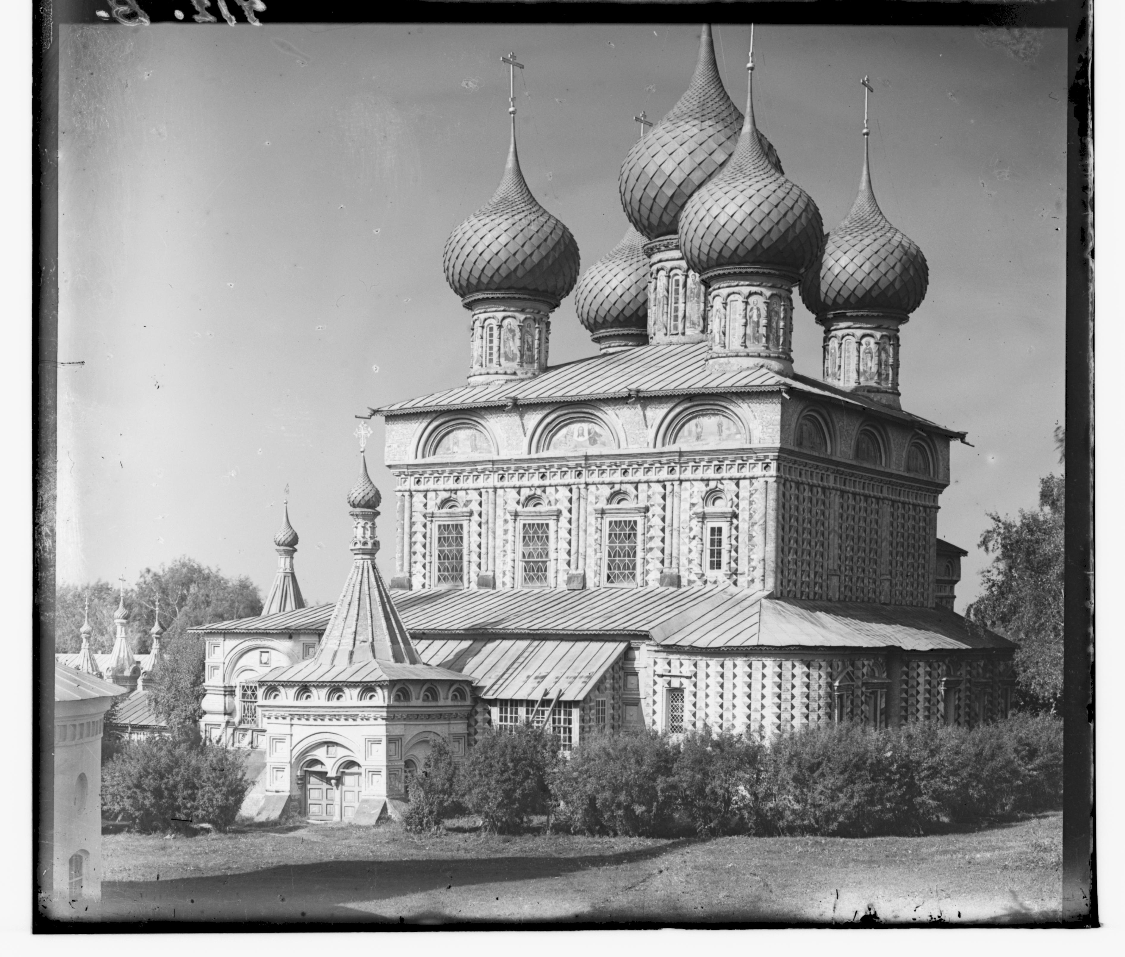
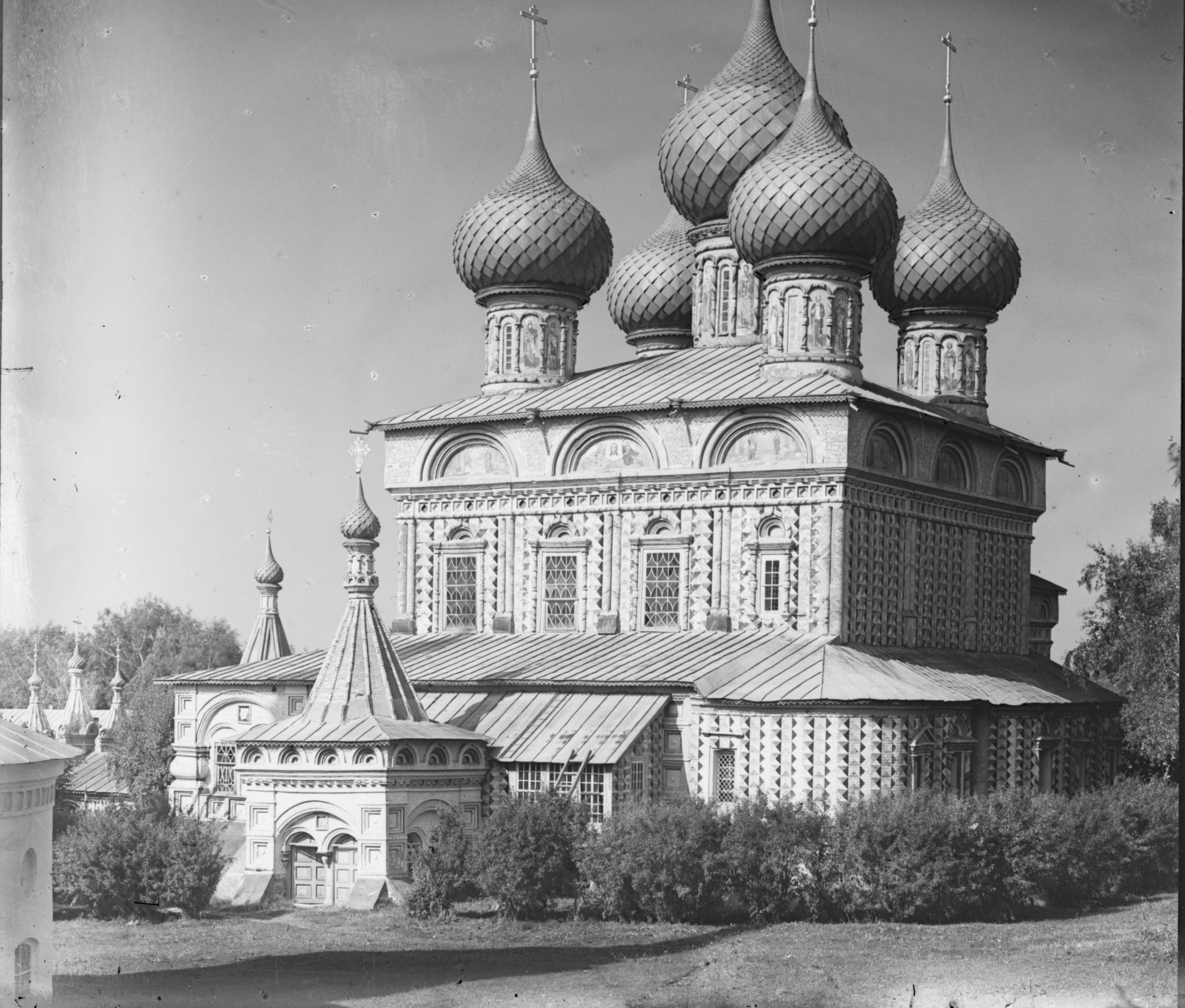
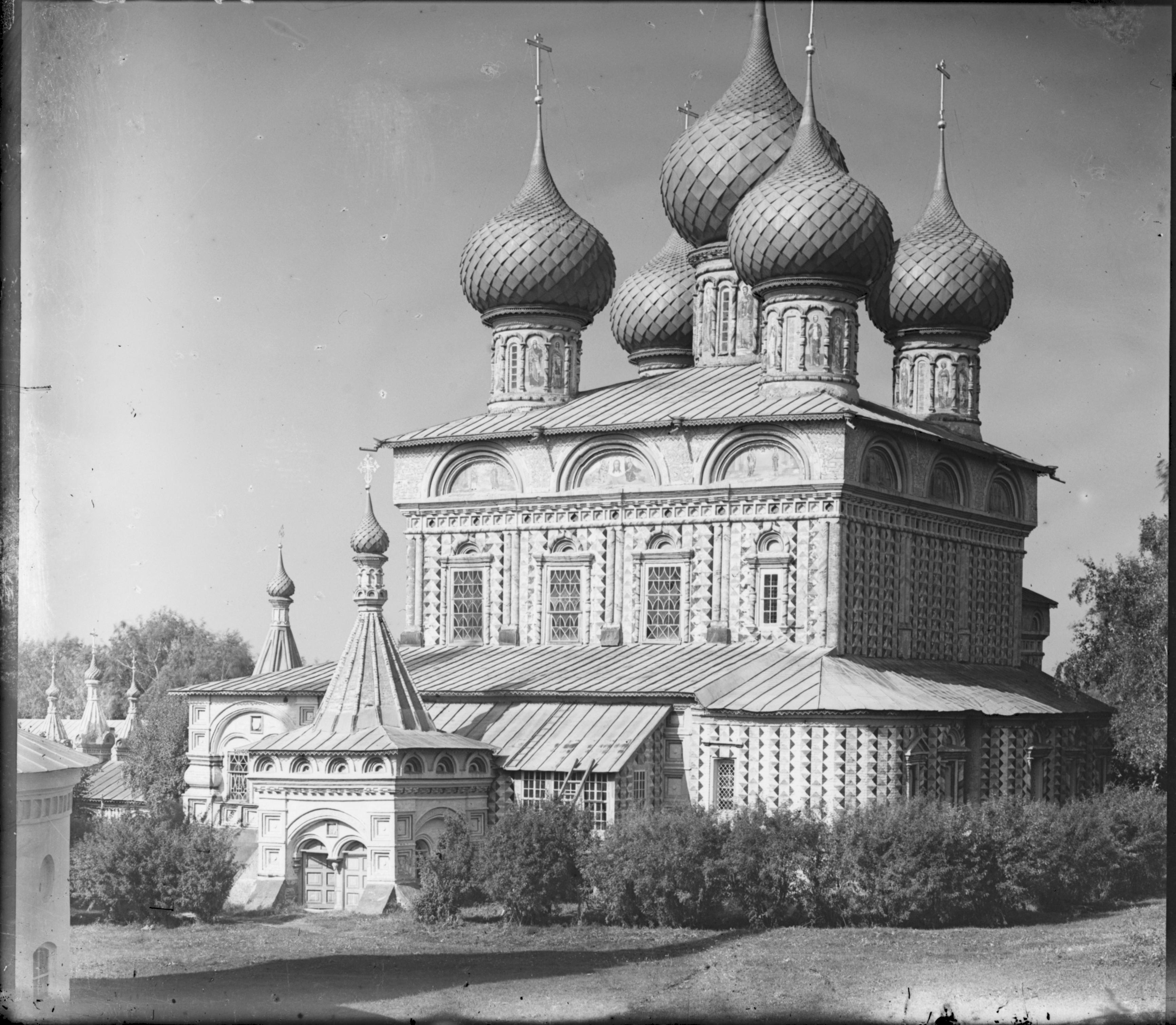
In addition to aligning the images, I implemented an automatic cropping algorithm that detects the borders of the channel images. First, we set all the darker pixels values ranging from 0 to 0.1 to 0 (black). Then, we consider a 5% margin of the channel image and crop out the row or column within if the amount of pixel values equaling 0 exceeds 30% of the row or column. Effectively, we were able to preserve a greater amount of the original image than from cropping out a 5% margin on all sides.
Results are shown below for the channel without the crop, with 5% margin cropping, and the smarter automatic cropping method respectively. We can see that the automatic cropping method we implemented preserves more of the original image while still cropping the same amount of borders as the 5% margin cropping method.
|
|
|
|
|
|
|
|
|
|
|
|
|
|
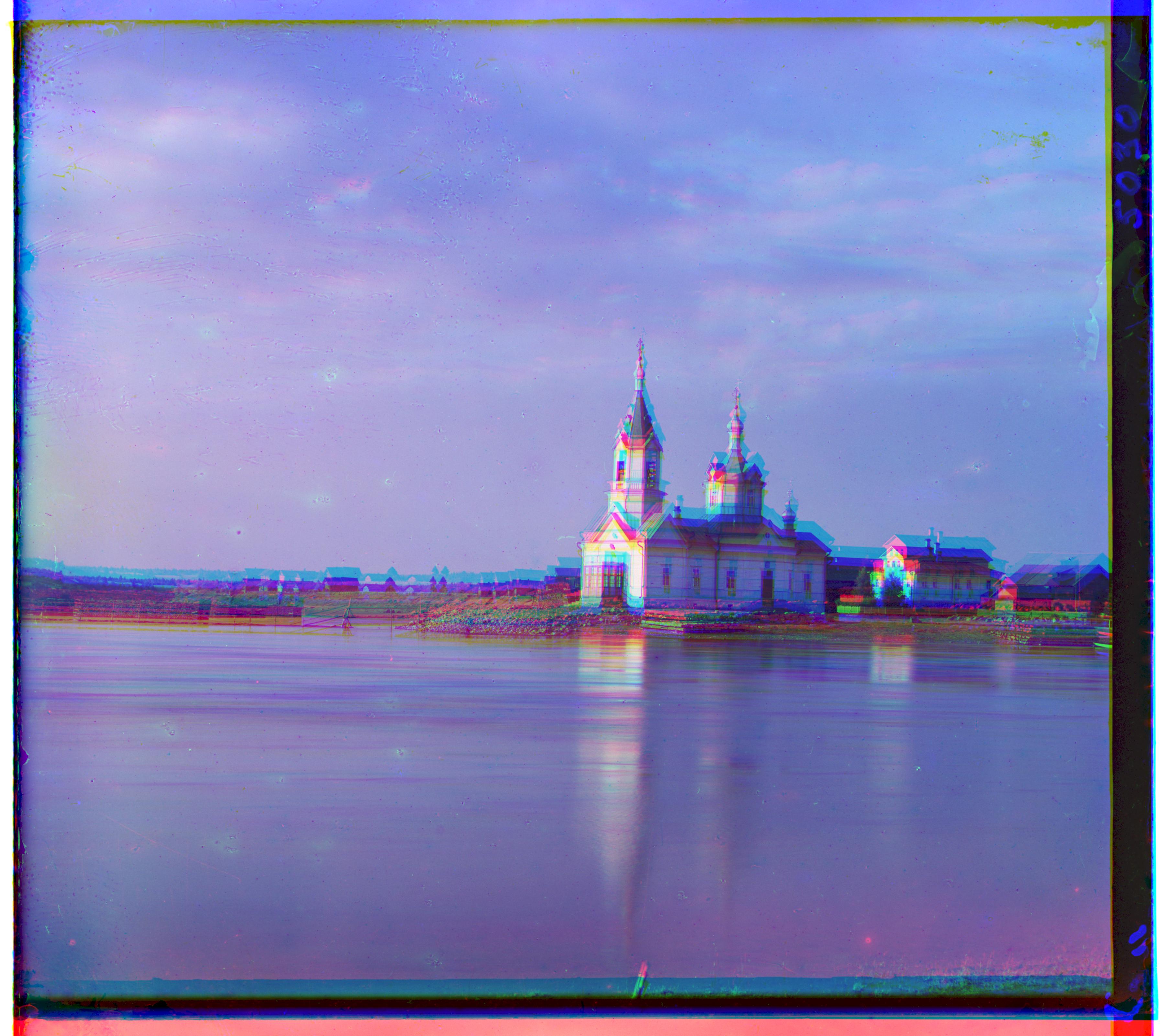
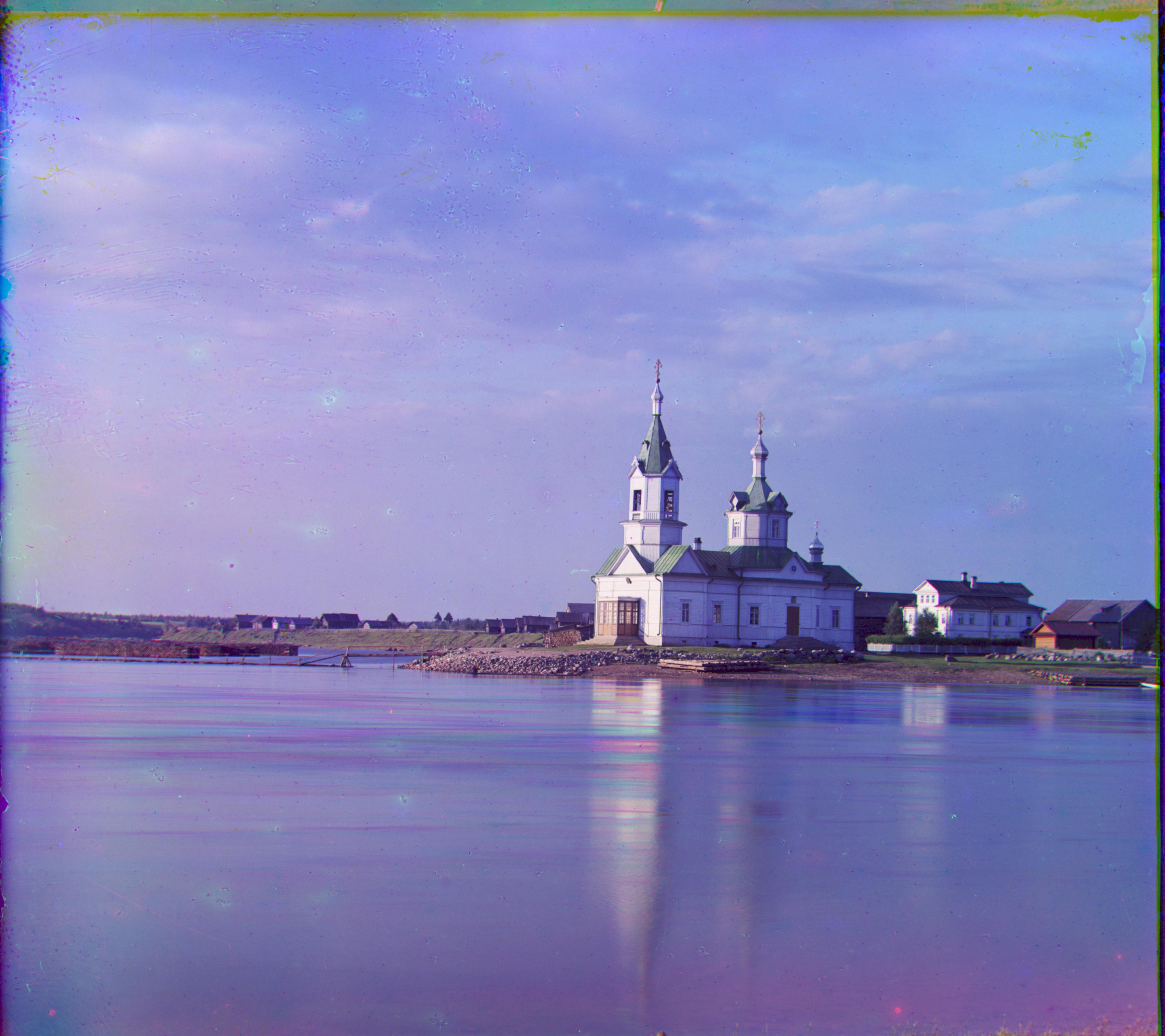
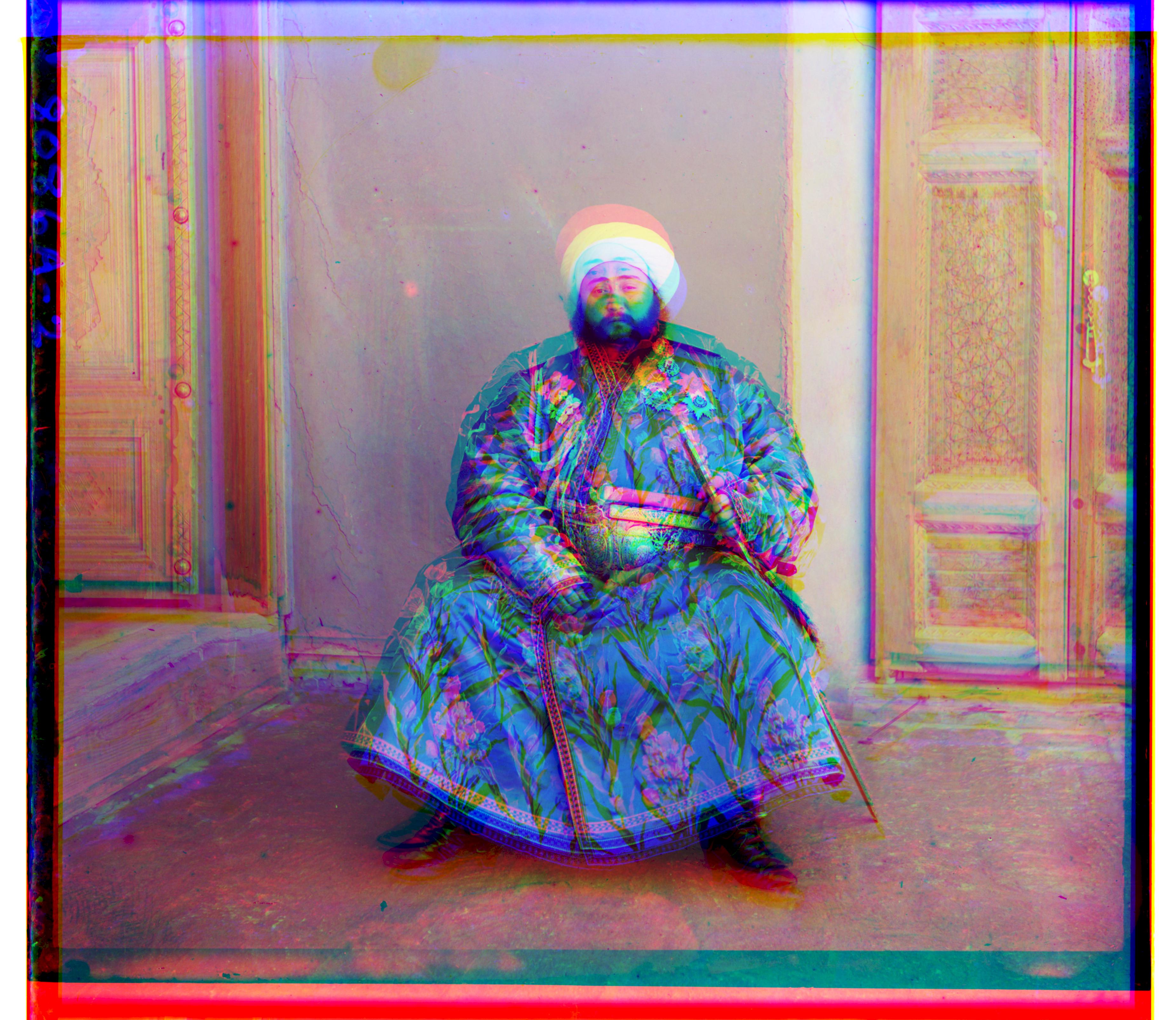
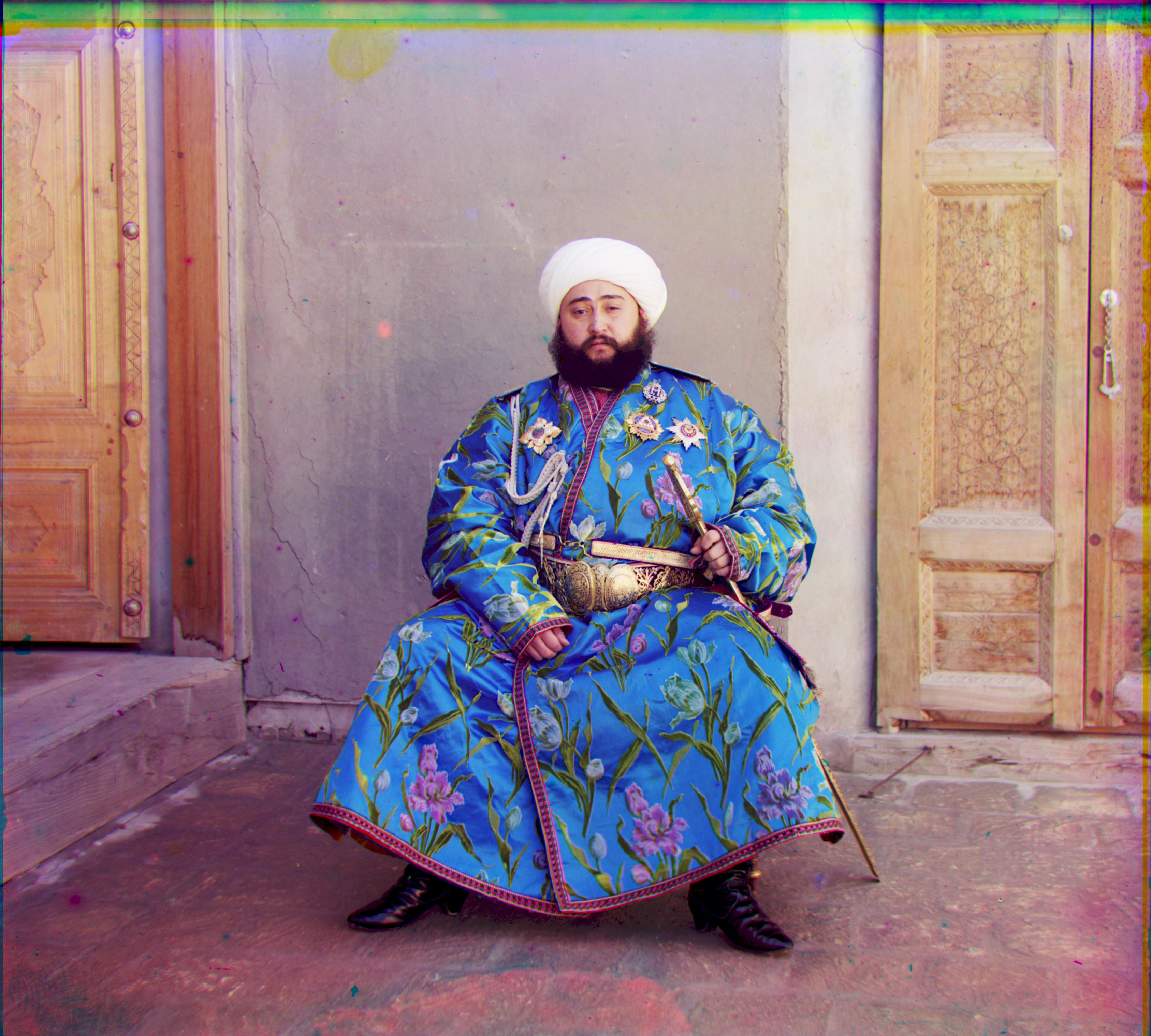
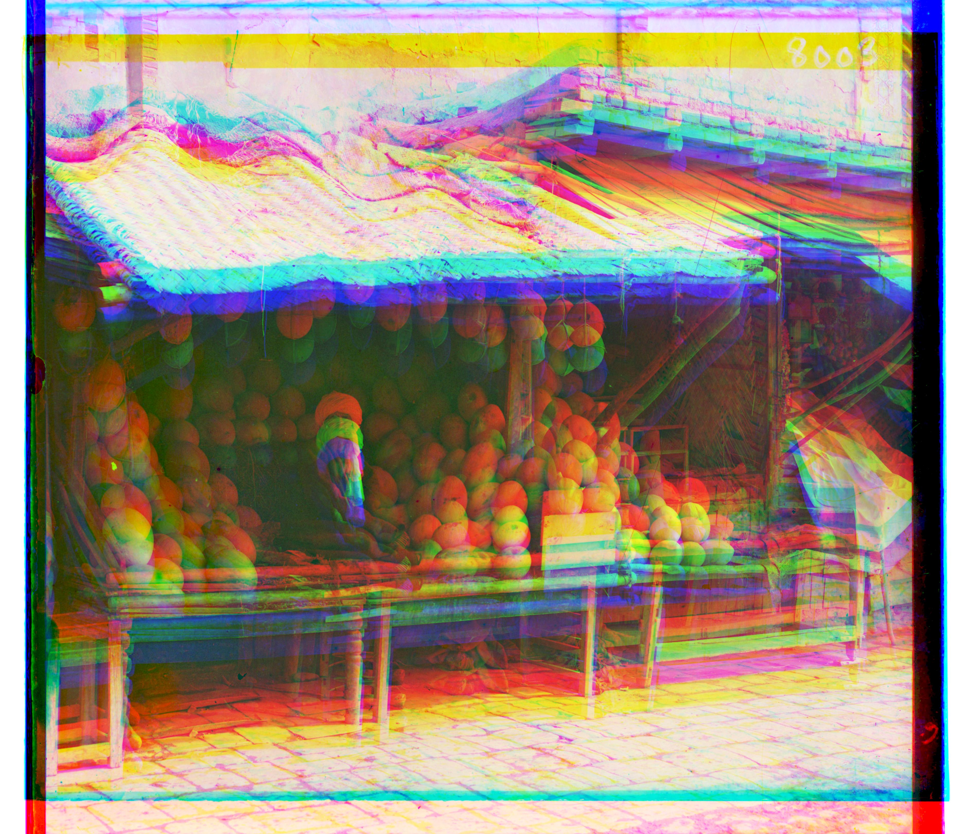
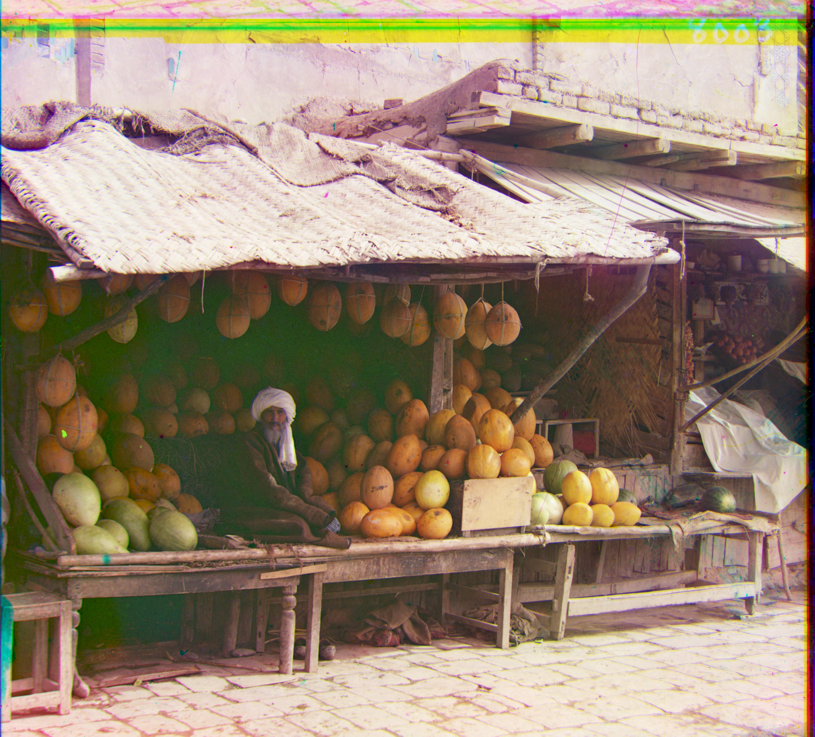
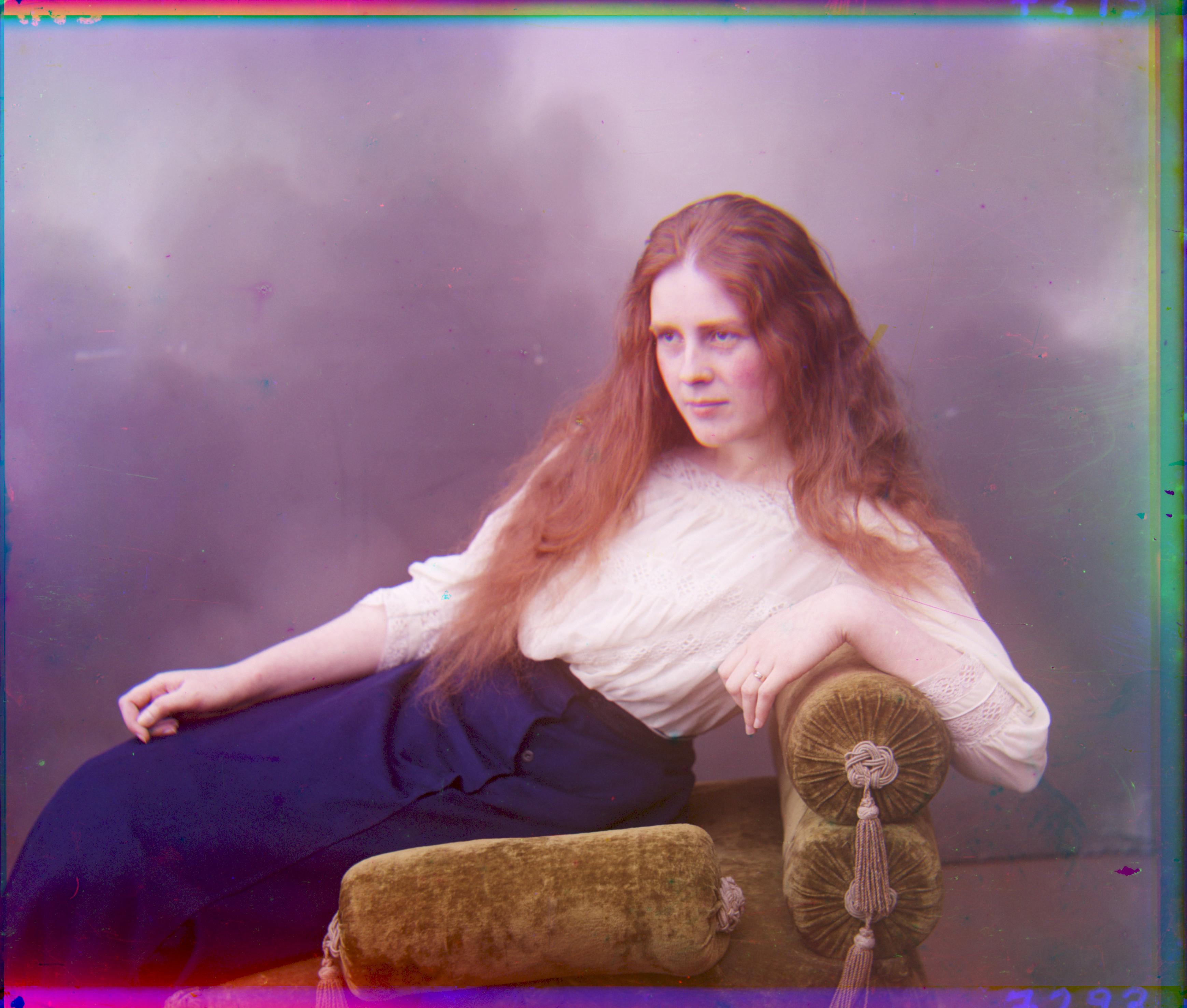
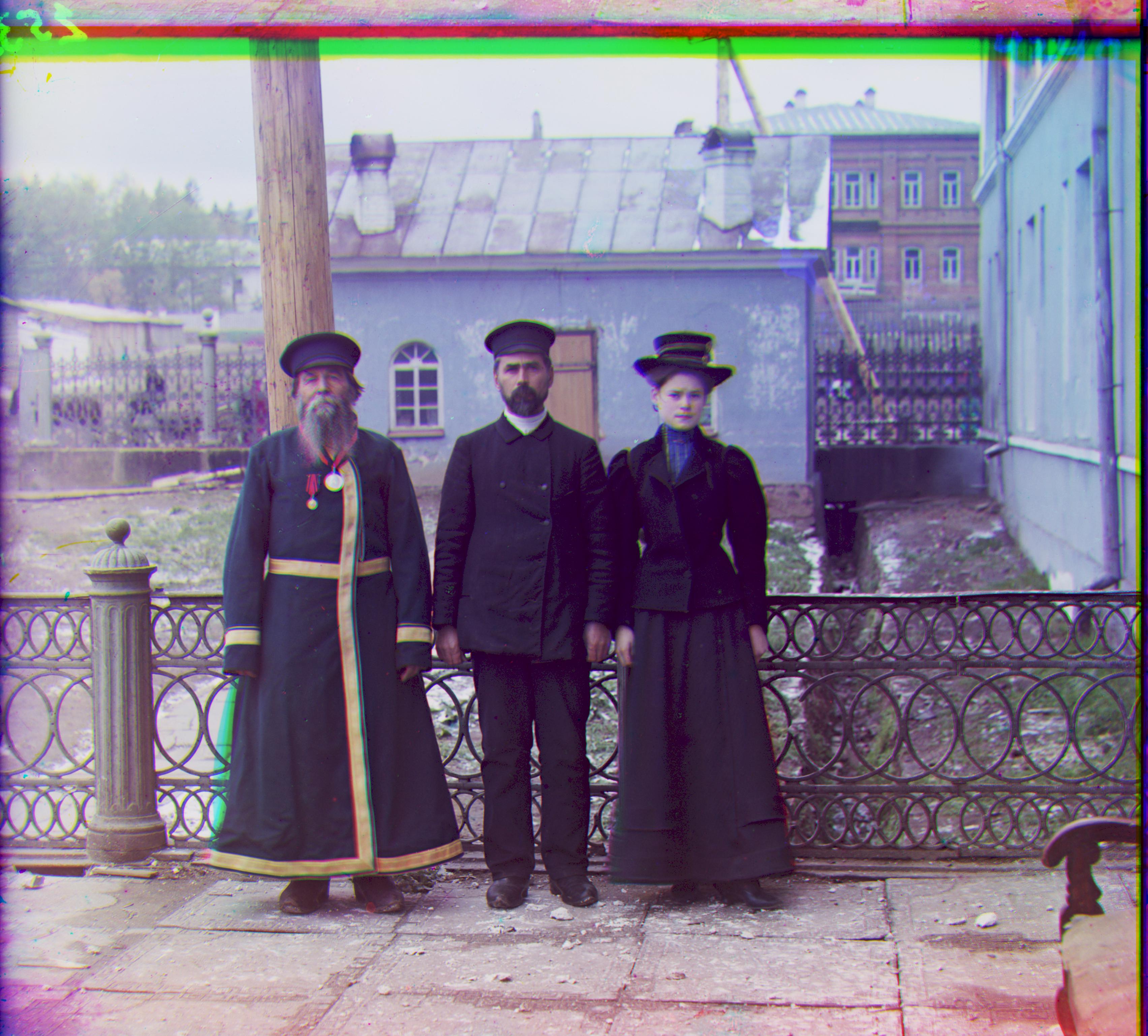
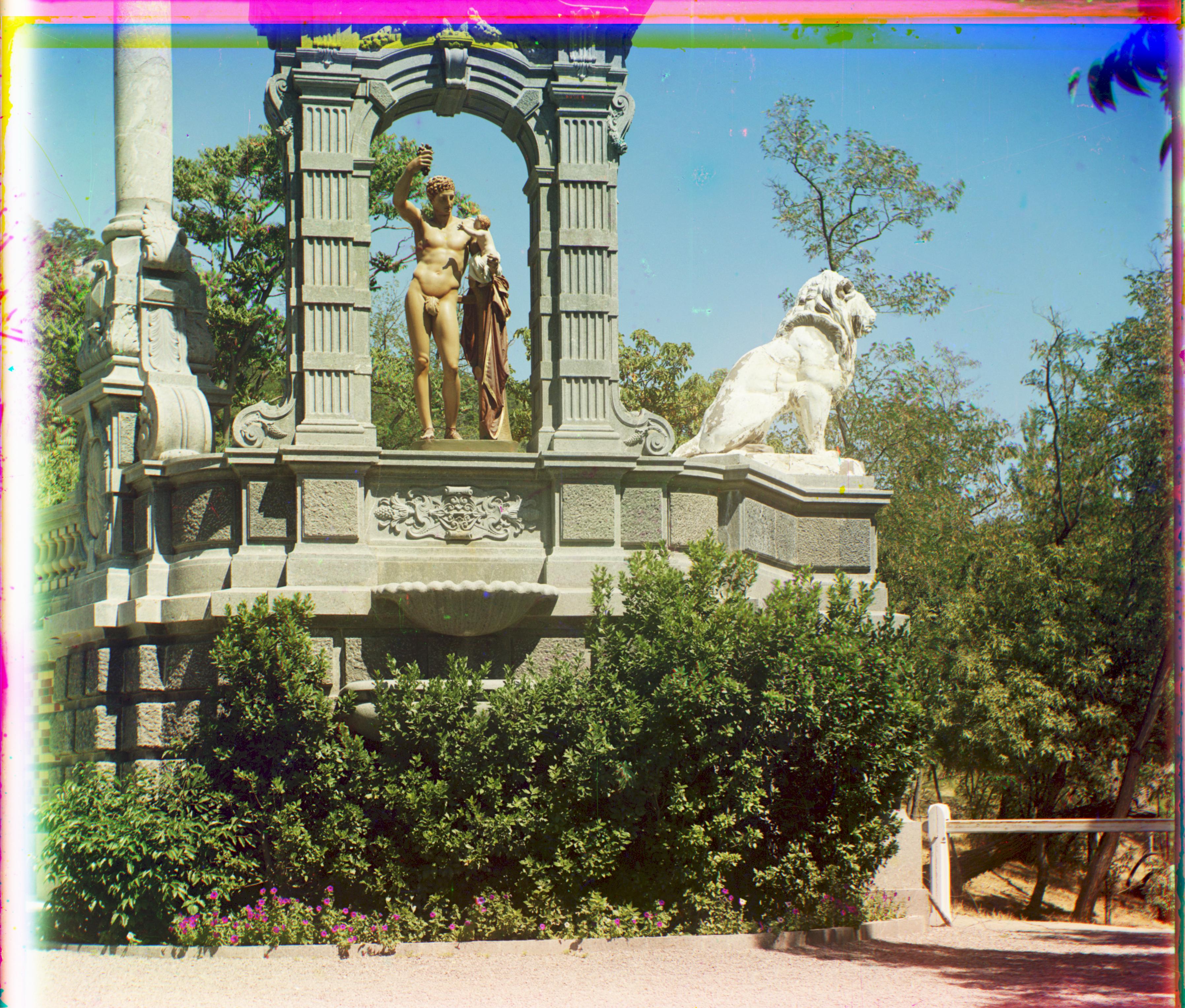
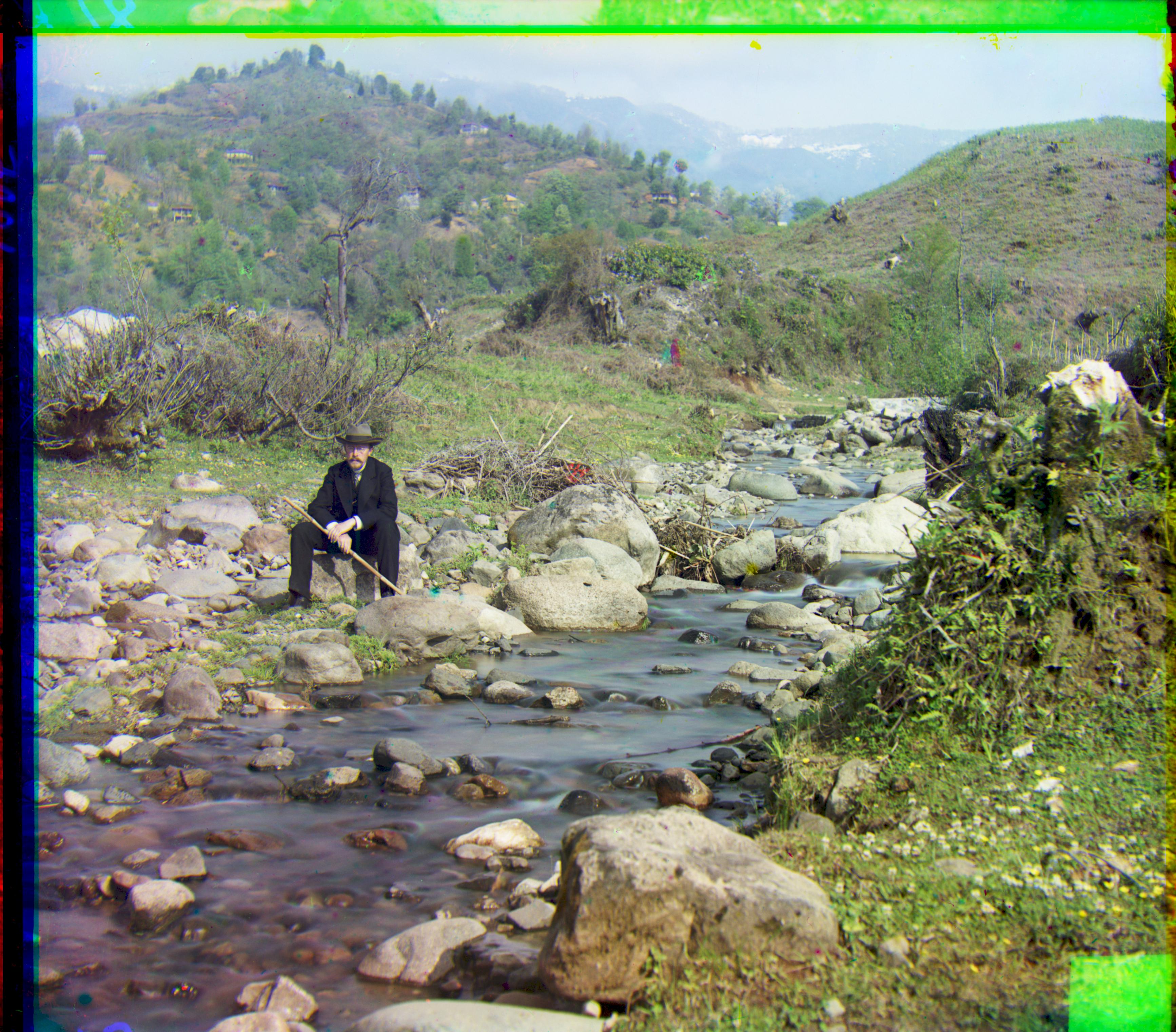
Below, we show the result of directly placing the filters on top of each other without alignment (raw data), and the result of displacing the channels via the pyramid method (processed data).
Raw Data |
Processed Data |
|
|
|
|
|
|
|

|
|
|
|
|
|
|